
Fiber Optic Connectors & Assemblies
Fiber Array Unit (FAU) Testing Solutions (New)(New)
Polarization-Maintaining Fiber Connectivity Components (New)(New)
Fiber Array (FA) Spot Alignment and Coupling Inspection System
SN-MT Connector Inspection Solutions for Manufacturing
MMC Connector Cleaning and Inspection Solutions for Manufacturing
MPO Connector Inspection Solutions
Automated Cleaning and Inspection for High-Speed Optical Transceivers
1.6T/800G Single-core Optical Module Intelligent Cleaning and Inspection Solution
1.6T/800G LC Optical Module Testing Scheme
Optical Port Cleaning and Inspection for Active Optical Devices
High-Speed Coherent Optical Transceiver Testing
Active Optical Cable (AOC) Testing Solutions
Linear Pluggable Optics (LPO) Testing
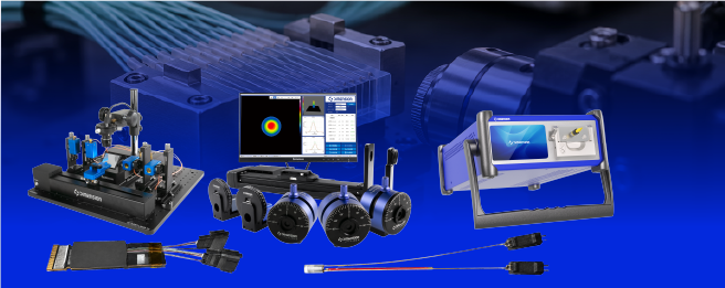
Optical Engine Testing Solutions
Dimension Technology is based on multi-channel optical power collection, wavelength spectrum measurement and automatic coupling. It integrates error detection, oscilloscope, electrical bias, etc., to
Applicable to the tested component
Suitable for the transmitting, receiving, and transmitting-receiving integrated optical engine for applications such as CPO, high-speed board-level optical interconnection, covering both external light source illumination and internal light source structure. The test boundary is defined around the optical engine itself and its accessible optical interfaces. The electrical interface rate, modulation format, and test reference plane are determined according to the design.

Test Focus
Establish separate links for transmission and reception, maintaining the prescribed electro-optical reference plane. For external light source type optical engines, the supply wavelength, power, and polarization conditions must be confirmed first; for multi-channel simultaneous measurement, it is also necessary to verify the power supply, heat dissipation, and inter-channel influence. The average power cannot be used as a substitute for the quality assessment of the link.
Solution Overview
External Light Supply and Optical Coupling Verification
Testing of the PPC multi-channel OPM and the automatic coupling fixture with external light source
Provide continuous light input according to the design for the external light source structure, monitor the power at the light supply end and output end, and verify the coupling loss and channel consistency. TLS can be used for the development wavelength scanning verification in the applicable wavelength band; for the finished product, high-speed testing uses the light source that meets the requirements of wavelength, power, polarization and noise, and cannot simply assume it is equivalent to the working light source due to its tunability.
For un-fixed interfaces, combine with fiber array probes, multi-axis positioning and power feedback to optimize coupling; for the finished product, use positioning fixtures and compatible connections. Polarization-maintaining light supply should be added for additional PER and axial checks.
Transmission end optical power, wavelength and spectrum testing
Multi-channel OPM wavelength meter and spectrometer
Measure the power of each transmission channel and its changes with current, temperature and operating status. The wavelength meter is used for measuring the wavelength and drift of laser output, while the spectrometer is used to observe WDM channels, spectral line distribution, edge modes and abnormal stray light; the resolution capability of the instrument needs to match the input signal characteristics.
The static spectral width measured by the spectrometer cannot replace the high-speed modulation quality, nor can it be directly used as the intrinsic linewidth of a narrow linewidth laser.

Transmission waveform and reception sensitivity test
BERT waveform or optical sampling analysis POA and power reference
For transmission test, input code patterns are specified through the electrical interface, and the optical waveforms and applicable OMA, extinction ratio and eye diagram indicators are measured; indicators such as TDECQ for PAM4 are configured according to the corresponding specifications, reference receiver and analysis methods. For reception test, a calibrated reference optical transmission signal is used, adjusted by the attenuator to the measured reference plane, and BER changes with input power are statistically analyzed.
Error detection requires retention of code type, rate, equalization or clock recovery settings, FEC aperture, statistical duration and error count. Reception sensitivity cannot be determined solely by OPM readings or electrical loopback.
Diagnosis and Automated Testing
Wavelength Response and Channel Isolation Verification
WST TopLight TLS PPC and Multi-channel Power Acquisition
For structures with accessible passive optical paths or measurable receiving monitoring quantities, perform wavelength response, passband, and channel isolation tests. The optical input to optical output and optical input to electrical output are respectively configured with detection links; the active modulation or receiving functions cannot directly apply the passive IL measurement model.
Optical path reflection diagnosis and assembly troubleshooting
OFDR and the corresponding test fixture
Analyze the reflection distribution near the connectors, tail fibers, and coupling interfaces for passive connection paths that can be disconnected, isolated in the receiving link, and returned. This is used for research and anomaly analysis. Before this, it is necessary to verify the path, resolution capability, and distance model; OFDR does not undertake eye diagram, bit error, or emission spectrum testing.
Temperature control, aging and multi-channel automatic testing
Temperature control fixtures, power monitoring, automated fixtures and test software
Maintain the operating temperature of the device according to the thermal design and monitor voltage, current and power consumption. Re-test power, wavelength, waveform and BER at the specified temperature or aging stage. Integrate scanning, loading and unloading, photoelectric connection and coupling confirmation; and measure the results of each channel separately and record them. Verify the crosstalk and performance changes caused by simultaneous excitation as required.
Scheme Advantages
Covering optical supply and high-speed transmission and reception links
Organizing tests based on external or internal light source structures, correlating static optical parameters with high-speed signal quality.
Automating coupling access tests
Incorporating light search, position maintenance, and power confirmation into the formula, adapting to assembly processes and finished product fixtures.
Adapting to different light engine structures
Selecting wavelength spectra, WST, OFDR, or high-speed transmission and reception measurements according to the emission, reception, and passive interface.
Related products and system configuration
Instrument or system | Main purposes and applicable conditions |
Testing the light sources: TopLight TLS and PPC | Light supply verification, research and development of wavelength tuning and polarization control |
Multi-channel OPM and POA | Power monitoring, receiving power setting and reference calibration |
Wavelength meter and spectrometer | Testing for wavelength drift and spectral distribution of the output |
BERT and reference optical transmission link | Code type excitation, received BER and sensitivity test |
Scanning or optical sampling and analysis system | Analysis of the transmission waveform and the applicable modulation quality |
Coupling probe array fixture and multi-axis platform | Unfixed optical port's light search and automatic alignment |
WST wavelength scanning system | Verification of wavelength response and channel isolation for the applicable optical path |
OFDR | Reflection and Fault Diagnosis for Passive Connection Paths |
Power supply, temperature control and automation testing platform | Power consumption monitoring, temperature re-measurement and multi-channel process management |
Select the necessary items based on the function of the tested component. The band, interface, bandwidth, accuracy and automation cycle should be confirmed according to the requirements of the project. The accompanying photoelectric probe, high-speed instrument and environmental equipment can be integrated according to the system requirements.
Easily access services and support from Dimension
Want help or have questions?