
Fiber Optic Connectors & Assemblies
Fiber Array Unit (FAU) Testing Solutions (New)(New)
Polarization-Maintaining Fiber Connectivity Components (New)(New)
Fiber Array (FA) Spot Alignment and Coupling Inspection System
SN-MT Connector Inspection Solutions for Manufacturing
MMC Connector Cleaning and Inspection Solutions for Manufacturing
MPO Connector Inspection Solutions
Automated Cleaning and Inspection for High-Speed Optical Transceivers
1.6T/800G Single-core Optical Module Intelligent Cleaning and Inspection Solution
1.6T/800G LC Optical Module Testing Scheme
Optical Port Cleaning and Inspection for Active Optical Devices
High-Speed Coherent Optical Transceiver Testing
Active Optical Cable (AOC) Testing Solutions
Linear Pluggable Optics (LPO) Testing
Direct Attach Copper (DAC) Cable Testing Solutions
The transmission performance of the DAC passive copper cable is affected by the cable length, connection interface and channel coupling. The tests are organized around transmission loss, signal integrity and link bit error, integrating frequency domain and time domain measurements with end-point verification for the product development, sample comparison and mass production inspection, providing a complete evaluation basis.
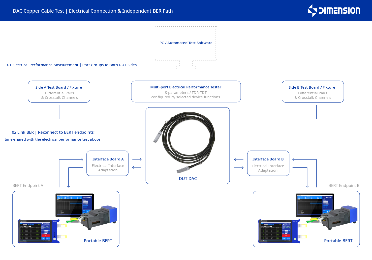
DAC copper cable test component diagram
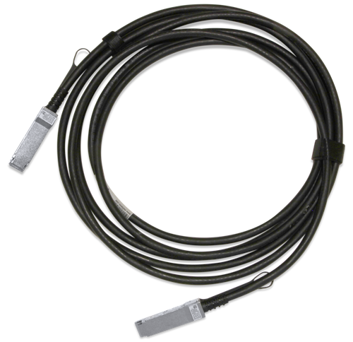
Our provided solution
We offer a test scheme for the loss, signal integrity and bit error of DAC copper cables, combining network parameter measurement, time domain analysis and dual-end bit error testing, to evaluate the transmission performance of the cable path and within the specified link respectively. Through unified channel management, curve determination and report output, it helps the mass production and delivery of DAC products of different lengths, interfaces and branch forms.
Transmission loss test
Multi-port electrical performance tester and dual-end test board
The two measurement ports of the multi-port electrical performance tester are respectively connected to the test boards at both ends of the DAC, and are connected according to differential channels and crosstalk combinations to obtain results such as insertion loss and return loss. The S-parameter testing platform, vector network analyzer or TDR/TDT resources with corresponding functions can be selected according to the project; before measurement, the calibration reference surface, fixture handling and unmeasured channel termination should be clearly defined to ensure the results correspond to the agreed measurement range.
Signal integrity test
Time domain reflection analysis and crosstalk measurement
By observing the discontinuous features of the cable and the connection interface through time domain impedance analysis, combined with near-end and far-end crosstalk measurement, the coupling influence between adjacent channels is evaluated. The abnormal curves are associated with specific channels to assist in the analysis and review of cable components and connection processes.
Bit error test
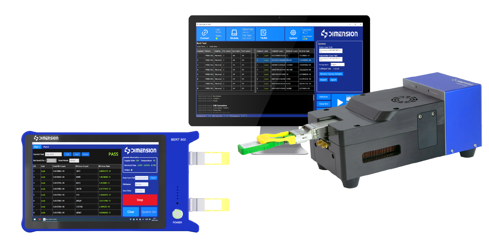
High-speed bit error instrument and transmission test end point
Connect the DAC to the matching transmission and reception end points, and test each channel for bit errors under the specified signal rate and equalization conditions. This section evaluates the transmission performance of the cable within the specified link and complements the loss, impedance and crosstalk results; the electrical performance and bit error items use their respective adapted measurement paths.
Interface adaptation and data management
Customized test fixtures and test software
Configure dual-ended test boards and cable loading structures according to interface, length and branch form, and unify channel mapping and project invocation. The software correlates product identification, test conditions, measurement curves and error code results, and outputs classification determination and reports, facilitating model switching and batch quality comparison.
The DAC itself is an passive transmission path, and errors are measured at the configured transmitting and receiving endpoints. Loss, signal integrity and error code tests are configured separately and retain corresponding conditions.
Typical test process
Product and channel confirmation
Fixture and path inspection
Loss and signal integrity
Link error code verification
Classification determination and report
Advantages of the plan
Support mass production
Electrical performance and transmission results are complementary
At the same time, loss, reflection, crosstalk and error code information are retained, facilitating the distinction between abnormal passive path conditions and differences in test link conditions.
Adapt to multi-specification production
Manage channel mapping and determination conditions by length, packaging and branch form, supporting switching of the same series of products and screening of key projects.
Abnormal results can be retested
Record test boards, connection paths, measurement curves and error code conditions, providing a basis for rechecking of defective channels and process improvement.
Easily access services and support from Dimension
Want help or have questions?