
Fiber Optic Connectors & Assemblies
Fiber Array Unit (FAU) Testing Solutions (New)(New)
Polarization-Maintaining Fiber Connectivity Components (New)(New)
Fiber Array (FA) Spot Alignment and Coupling Inspection System
SN-MT Connector Inspection Solutions for Manufacturing
MMC Connector Cleaning and Inspection Solutions for Manufacturing
MPO Connector Inspection Solutions
Automated Cleaning and Inspection for High-Speed Optical Transceivers
1.6T/800G Single-core Optical Module Intelligent Cleaning and Inspection Solution
1.6T/800G LC Optical Module Testing Scheme
Optical Port Cleaning and Inspection for Active Optical Devices
High-Speed Coherent Optical Transceiver Testing
Active Optical Cable (AOC) Testing Solutions
Linear Pluggable Optics (LPO) Testing
Optical Isolators and Circulators
The optical isolator only allows light to transmit in one direction and blocks the reverse-reflected light that interferes with the light source. It is a passive device. The optical circulator, in accordance with the port sequence, directs the light path and realizes the separation of the receiving and transmitting signals. It is also a passive device.
Solution Overview
This solution conducts performance tests on optical isolators and optical circulators. Under specified working wavelengths, temperatures, and input optical power conditions, a test link is established using tunable light sources, optical power meters, and polarization controllers. The insertion loss, isolation degree, return loss, and polarization-dependent loss of the optical isolator are tested; the insertion loss, crosstalk (isolation degree), return loss, and polarization-dependent loss of each path of the optical circulator, as well as its directionality are tested. At the same time, the stability of the device under forward light transmission, reverse/other port isolation states is verified. The changes in indicators under different polarization states are recorded, and the optical performance of the device is determined to see if it meets the specification requirements.

Core test parameters:
一、Optical isolator
1. Insertion loss IL:The optical power attenuation caused by the device when light is transmitted in the forward direction, indicating the forward light transmission capability.
2.Isolation degree ISO :The ability of the device to suppress the reverse light, measuring the effect of blocking the reflected light from bouncing back to the light source.
3.Return loss RL:The size of the reflected light that enters the end face / interior of the device and returns along the original input port, reflecting the level of end face reflection.
4.Polarization dependent loss PDL :The maximum difference in insertion loss of the device when the incident light polarization state changes, representing the sensitivity of the device to polarization.
二、Ring circulator (taking the three-port version as an example: 1→2,2→3)
1.Insertion loss IL(1→2、2→3):Specifies the optical power attenuation of the forward transmission path, which is the transparency indicator of the main path.
2.Port crosstalk( isolation degree):The size of the optical leakage from the non-conductive ports. For example, the leakage from port 1 when light enters port 3, or the leakage from port 2 when light enters port 1. It characterizes the isolation ability between ports.
3. Return loss RL(each port):The size of the reflected light from the end face and internal structure of each port, preventing reflection interference with upstream devices.
4.Polarization dependent loss PDL(each forward path):The maximum fluctuation value of insertion loss under the same path, when the insertion loss varies with the polarization state.
5.Directivity:The suppression ability of the main path of the ring circulator for the forward transmission light and the reverse stray leakage light.
Output power and power stability test
Measures the output optical power of the tested component and observes the change of power over time through continuous collection, which is used to evaluate the output level and stability. The OPM optical power meter provides various module and channel configurations, and can be combined with the test platform to build a single-channel or multi-channel power measurement system.
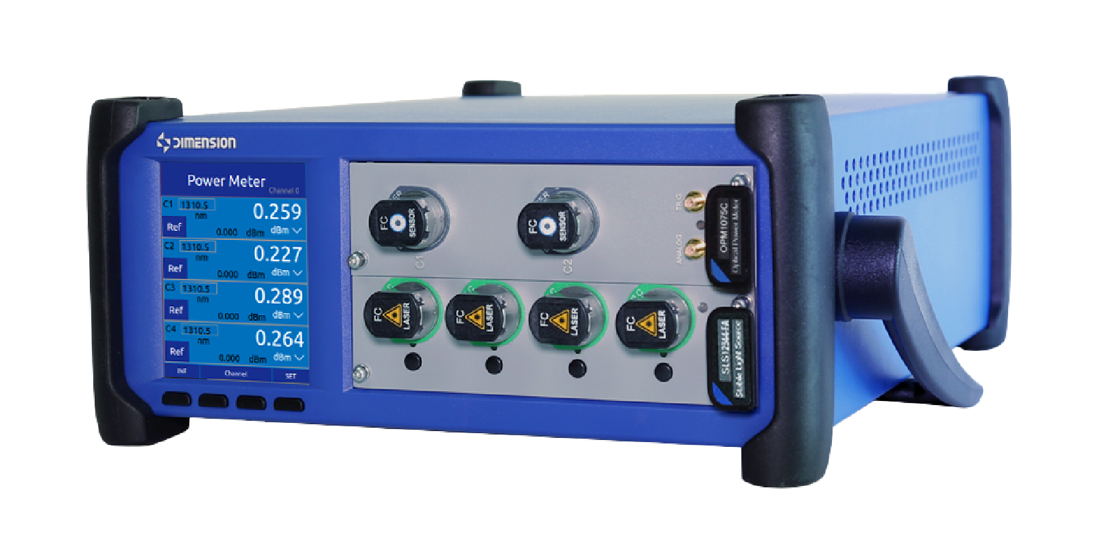
Multi-channel optical power meter
Spectral performance test
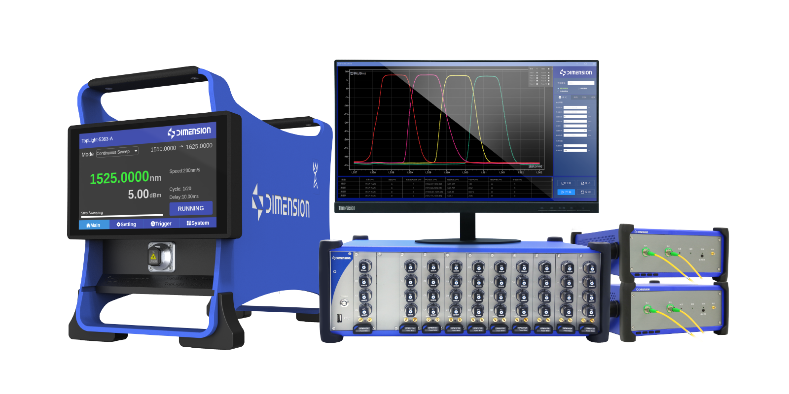
Calibration of adjustable light source and power meter for spectral testing
Measure the central wavelength, spectral width and edge mode suppression ratio to evaluate the spectral characteristics of the laser output. Select a spectral analyzer according to the wavelength range, spectral width and edge mode suppression ratio requirements of the measured object, and correlate the spectral results with the polarization and power test results to form a complete performance record.
Multi-channel optical path switching
By using the optical switch to connect different measurement channels or testing instruments, the need for repeated plugging and unplugging is reduced, making it easier to construct a multi-channel testing process. OSW can be configured according to the number of channels and interface forms; for applications requiring light input monitoring, a testing system can be built in combination with a power monitoring scheme. The PER measurement link needs to be verified separately to avoid the impact on the results due to the change of polarization state when switching the link.
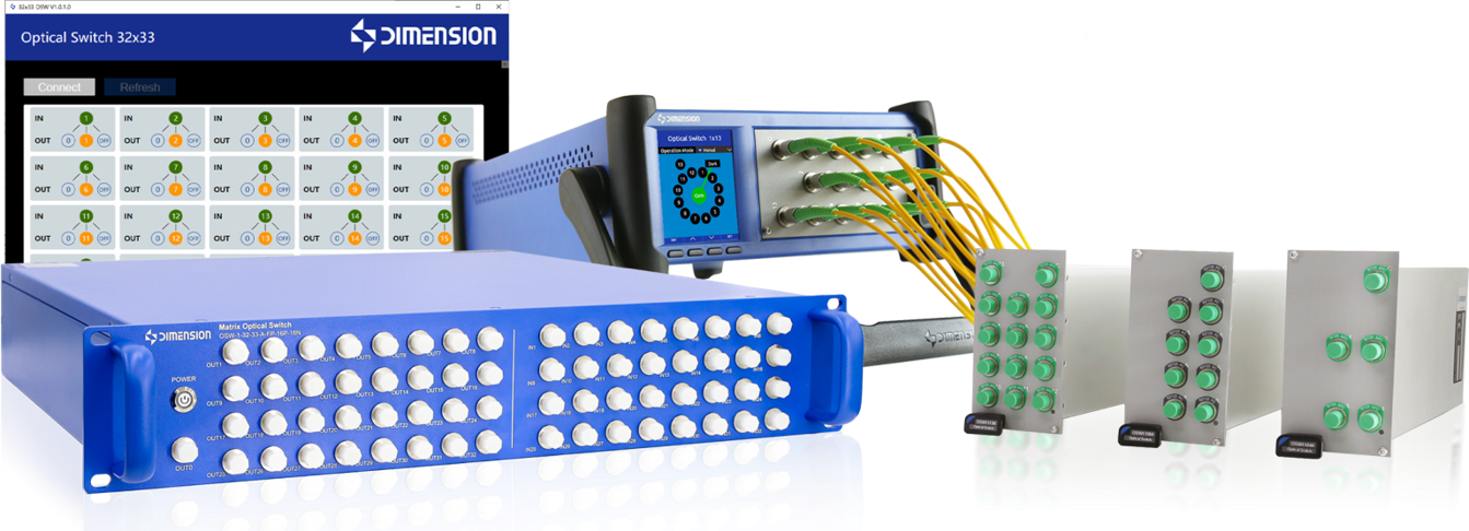
OSW optical switch
Optical fiber end face defect detection
FastCheck Pro fully automatic optical fiber end face detector
EasyGet WiFi handheld end face detector
MT SCOPE handheld end face detector
Check for contamination, scratches and other defects on the connection end face, reducing interference to power and polarization measurements caused by the connection status. FastCheck Pro supports automatic centering, focusing, exposure and measurement, suitable for bench-top detection and integration with automation; EasyGet WiFi supports wireless transmission, automatic analysis and report output; MT SCOPE comes with a touch screen and can independently complete on-site detection and determination. Specific interfaces require corresponding adapters.
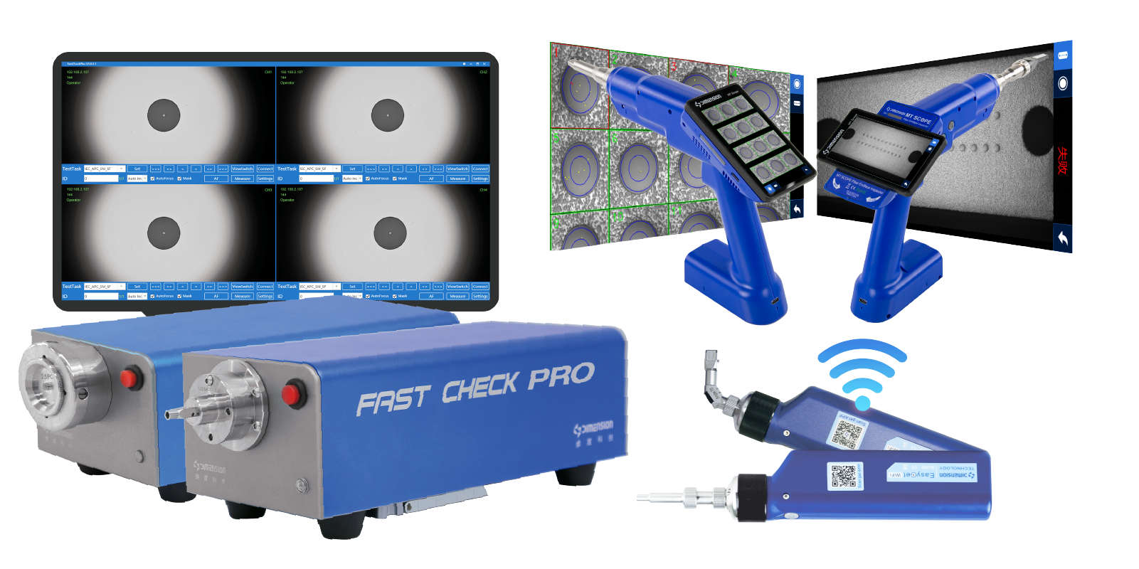
End face detector
End face cleaning
Offsoon Pro Optical Fiber End Face Cleaning Equipment
This equipment adopts a non-contact cleaning method using a cleaning solution combined with dust-free gas to remove oil stains and adhered contaminants on the connection end faces. It is recommended to confirm the end face condition following the "inspection - cleaning - re-inspection" process. Re-inspection must be successful before connecting to the performance test link; the cleaning head and process are configured according to the interface structure.
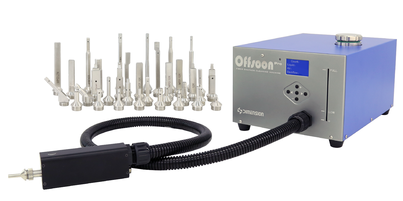
Offsoon Pro Optical Fiber End Face Cleaning Equipment
Advantages of the plan
1. Comprehensive coverage of indicators
It covers the core optical indicators of isolators and circulators (IL/ISO/RL/PDL/crosstalk/directivity), taking into account both forward transmission performance and reverse isolation, reflection suppression capabilities, and meets the full-item verification requirements of the device specification.
2.Polarization state traversal verification
Introduce polarization controllers to scan the entire polarization state, capture PDL fluctuations, avoid index misjudgment under a single polarization test, and better match the random polarization usage scenarios of the actual optical path in the field.
3.Generalized test link reusability
Core instruments such as light sources, optical power meters, polarization controllers, and return loss meters share a single platform. By adjusting the optical path connection method, the isolator can be switched.
4.Circulator testing, reducing instrument setup time
Quantifiable and reproducible: Each parameter is clearly defined, the test logic is standardized, the operation steps are fixed, and the test results of different testers and different batch samples are highly consistent, making it convenient for comparison and archiving.
5.Close to real working conditions
Test under nominal working wavelength and rated input optical power, evaluate the real performance of the device in suppressing reflected light, splitting and receiving isolation in the actual system, and identify application risks in advance.
6.Hierarchical determination
Data can be independently collected by channels and ports, and the crosstalk of each path and port of the circulator is recorded separately. This facilitates the identification of single-port/single-path failure issues.
Easily access services and support from Dimension
Want help or have questions?