
Fiber Optic Connectors & Assemblies
Fiber Array Unit (FAU) Testing Solutions (New)(New)
Polarization-Maintaining Fiber Connectivity Components (New)(New)
Fiber Array (FA) Spot Alignment and Coupling Inspection System
SN-MT Connector Inspection Solutions for Manufacturing
MMC Connector Cleaning and Inspection Solutions for Manufacturing
MPO Connector Inspection Solutions
Automated Cleaning and Inspection for High-Speed Optical Transceivers
1.6T/800G Single-core Optical Module Intelligent Cleaning and Inspection Solution
1.6T/800G LC Optical Module Testing Scheme
Optical Port Cleaning and Inspection for Active Optical Devices
High-Speed Coherent Optical Transceiver Testing
Active Optical Cable (AOC) Testing Solutions
Linear Pluggable Optics (LPO) Testing
High-Speed Electrical Connector Testing Solutions
Dimension Technology offers insertion loss, return loss, crosstalk and time-domain analysis solutions for pairing and connection components, supporting design verification, selection comparison and ma
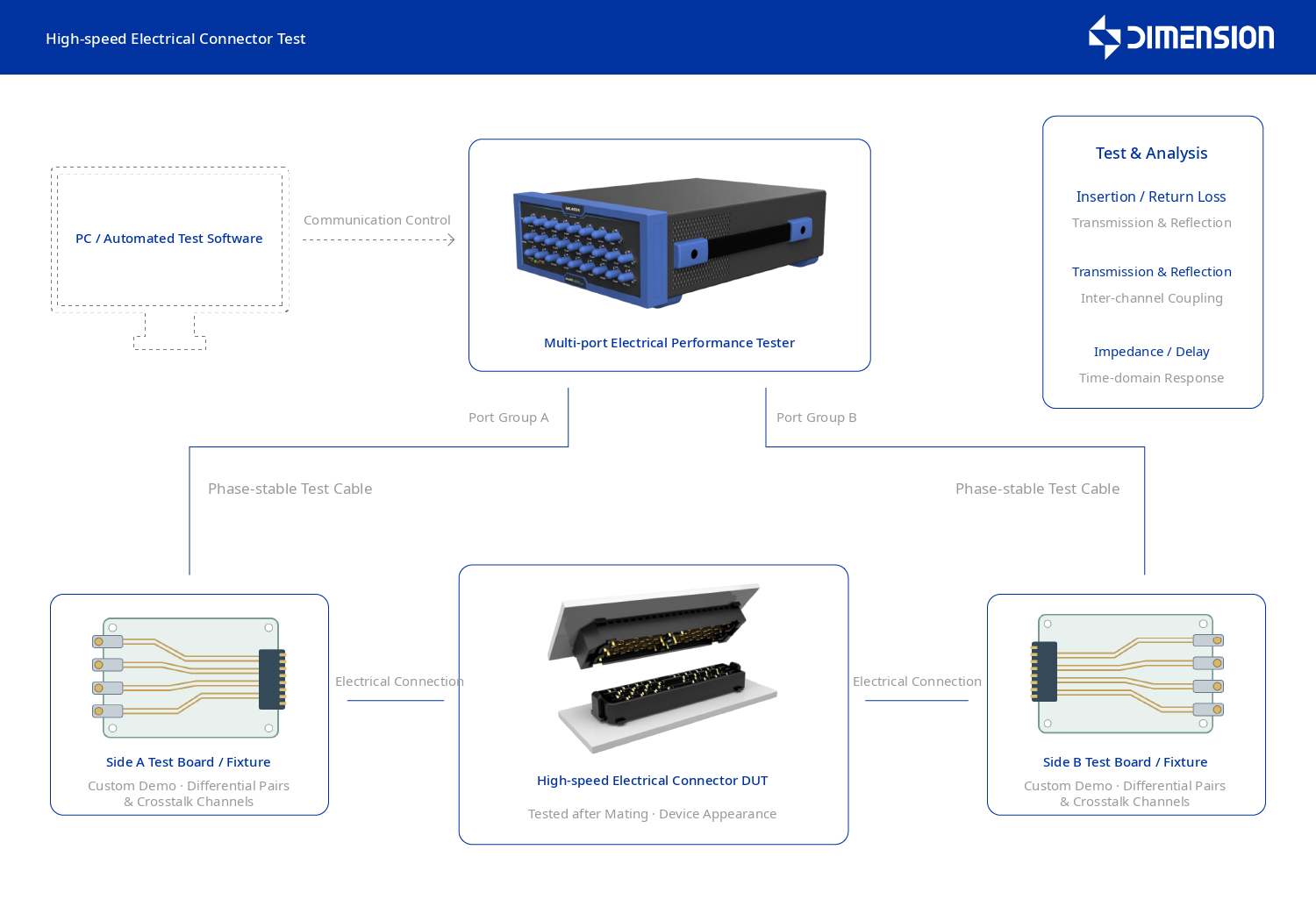
High-speed electrical connector test component diagram
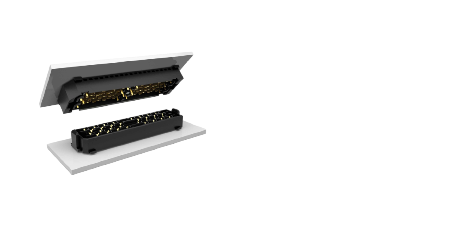
Our provided solution
We offer a signal integrity testing solution for high-speed electrical connectors. Taking connector structure, mating scheme and pin definition into consideration, the solution is equipped with test boards, connection fixtures and electrical measurement resources. Through differential channel measurement, curve comparison and limit judgment, it evaluates the attenuation, reflection and crosstalk coupling characteristics of the connection path, supporting product verification, mass production launch and quality control.
Insertion loss and return loss testing
Multi-port electrical performance tester and pairing test board
Connect the two sets of measurement ports of the instrument to the test boards on both sides of the pairing connection component, organize the connection according to the target differential pair and crosstalk channel, and obtain the transmission loss and reflection results. Select the network parameter or time domain measurement platform with corresponding capabilities based on the project, clarify the installation structure, calibration reference surface and fixture influence handling method, and then compare the performance of each channel and samples.
Cross-talk test
Multi-port measurement and channel connection components
Select the disturbed and interfered channels according to pin definitions and signal, ground distribution, measure near-end and far-end cross-talk. Compare different differential pair combinations, evaluate channel coupling of high-density connection interfaces, and provide data for layout optimization and product specification determination.
Signal integrity analysis
Time-domain reflection and time-domain transmission analysis
Obtain time-domain characteristics such as impedance and transmission delay by project configuration, and combine with frequency-domain loss and crosstalk curve analysis to analyze the connection path.
Test adaptation and curve determination
Paired test fixtures and analysis software
Configure the test board and positioning mechanism according to the connector shape, pairing method and installation structure, and unify the pin mapping, measurement path and curve limits. The software will associate the results with the product and differential pairs, output test reports and comparison records, and support R&D evaluation and mass production screening.
The measurement boundaries of connectors, mating parts and test boards need to be clearly defined, and the influence of fixtures will be handled according to the agreed method.
Typical testing process
- Pairing and pin confirmation
- Loading and measurement preparation
- Loss and crosstalk testing
- Time-domain characteristic analysis
- Curve determination and report
Solution Advantages
Support mass production
Maintain consistent sample testing conditions
Unify pairing status, installation method and channel number to establish consistent conditions for comparisons between different samples and batches.
Select projects based on product stage
During the research and development stage, focus on the complete curve and channel characteristics. During the mass production stage, key project screening can be configured as required, taking into account evaluation needs and test cycle.
Curve results are associated with differential pairs
Save loss, crosstalk and impedance results, associate pin combinations with tooling information, and support abnormal re-testing and design version comparison.
Easily access services and support from Dimension
Want help or have questions?