
Fiber Optic Connectors & Assemblies
Fiber Array Unit (FAU) Testing Solutions (New)(New)
Polarization-Maintaining Fiber Connectivity Components (New)(New)
Fiber Array (FA) Spot Alignment and Coupling Inspection System
SN-MT Connector Inspection Solutions for Manufacturing
MMC Connector Cleaning and Inspection Solutions for Manufacturing
MPO Connector Inspection Solutions
Automated Cleaning and Inspection for High-Speed Optical Transceivers
1.6T/800G Single-core Optical Module Intelligent Cleaning and Inspection Solution
1.6T/800G LC Optical Module Testing Scheme
Optical Port Cleaning and Inspection for Active Optical Devices
High-Speed Coherent Optical Transceiver Testing
Active Optical Cable (AOC) Testing Solutions
Linear Pluggable Optics (LPO) Testing
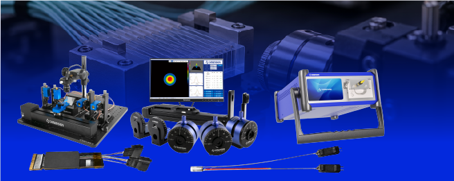
ELSFP External Light Source Testing Solutions (NEW)
The ELSFP external light source provides continuous wave light to the CPO optical engine. The output quality and interface connection quality jointly affect the light supply performance of the system
Dimension Technology, based on the requirements of ELSFP's research and development, production testing, and incoming material inspection, has proposed a modular solution integrating optical power, polarization extinction ratio, wavelength and spectrum testing, as well as optical port detection and cleaning. By unifying fixtures, test formulas and data management, it organizes the scattered testing steps into a traceable testing process.
Figure 1 Schematic illustration of the application location of ELSFP. The diagram represents functional relationships and does not represent the internal structure of specific modules.
The difficult points to be addressed in the test
Testing difficulties | Plan concept |
The multi-channel results are not easily correlated. | Establish the mapping between ports, fibers and logical channels, and bind the test results for each fiber. |
PER is susceptible to the influence of the test link. | Establish an interface direction reference, using direct sunlight or verified polarization-preserving links. |
Pollution and residual liquid affect the connection quality. | After conducting bilateral end checks, performing clean rechecks, and confirming the low-power link, the power will be raised to the target level. |
The requirements for research and development are different from those for production line testing. | Unified system architecture, with instruments and processes configured according to all research and development items or the mandatory testing items of the production line. |
01 The modular architecture covers a variety of optical tests.
The system consists of an ELSFP test fixture, interface adapter fixtures, an optical measurement unit and an automated software. The test fixture is responsible for power supply, communication management and temperature condition control; the optical path is independently configured according to parameter requirements to avoid additional influence on polarization measurement caused by the general switching link.

Figure 2 Suggested test architecture. The PER branch is designed independently; the power capacity of the switching device and the polarization effect need to be verified.
Test Item | Pay attention to the content | Suggested measurement method |
Output power and stability | Per-core power, channel variance, time drift | High-power compatible power meter; records steady-state and time series |
Polarization extinction ratio (PER) | The power ratio in the interface direction and the polarization angle | Independent polarization analysis branch, single-core or multi-row scanning |
Central wavelength and drift | Wavelength and temperature drift under the specified operating conditions | Wavelength meter; synchronous recording of temperature and driving conditions |
Spectral-to-edge-mode suppression ratio | Spectral shape, edge mode and abnormal peak | OSA that meets the requirements of resolution and dynamic range |
Line width and RIN options | Frequency noise or intensity noise characteristics | Special line width system; photoelectric detector and electrical spectrum analyzer |
The various limits are determined by the module specification, the target application, and the customer acceptance conditions. The line width and RIN are configured as part of a research or specialized verification project; the spectral width reading of an ordinary spectrometer cannot directly replace the measurement of narrow line width.
02 The PER test is based on the interface benchmark.
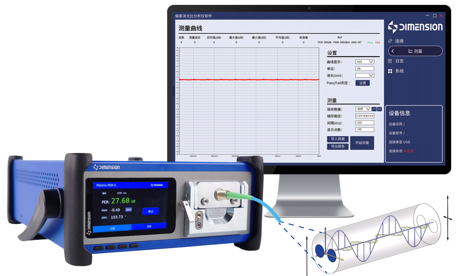
The polarization output should pay attention to both the polarization purity and the polarization direction. When conducting tests according to the OIF interface definition, the connection lines of the MT core guiding holes should be associated with the measurement coordinate system. Test-level polarization jumpers and calibration free-space devices can be used as different measurement paths. Which one to use should be consistent with the required test reference surface.

Figure 3: Direct daylighting and multi-core positioning concept for PER. The directions of the two types of PER readings should be recorded separately.
Directly utilizing natural light reduces the uncertainty introduced by the transmission link.
It is suggested to design and fabricate fixtures specifically for the ELSFP optical interface, so that the light output can directly enter the polarization analysis unit after passing through the light collection optical system. By moving in the X and Y directions, different rows and columns of the optical fibers can be covered; the fixtures simultaneously constrain the posture and repeat the clamping position, and record the zero point of the interface direction.
Take the polarization angle deviation into account in the results
The maximum and minimum power ratio obtained by the rotation analyzer reflects the maximum PER of the collected beam; the PER relative to the specified direction of the interface is also affected by the polarization angle deviation. Therefore, the report should simultaneously save the interface reference PER, the maximum PER, and the polarization angle to prevent allowing passage based solely on the maximum value.
Supporting the application of the production line with repeatable verification
Carry out repeated clamping, repeated scanning and cross-station comparison on the reference sample; check the light transmission numerical aperture, the analyzer's extinction capability, the detector's linearity and background noise. When using polarization maintaining jumper wires, it is necessary to verify the influence of rotational error, bending and temperature changes in the connection; PER cannot be simply corrected by subtracting dB as in the case of ordinary insertion loss.
03 Port detection and cleaning form a closed loop.

The interface between the module side and the host side of ELSFP should all be included in the end inspection scope. For high-power optical supply interfaces, contaminants and cleaning residual liquids may cause local damage; only the cleaning action record is not sufficient to prove that the port is available; a re-inspection image should be saved, and the link status should be confirmed before entering the normal power supply.

Figure 4 Suggests an automated testing process. For each step, a status record is maintained. Abnormal products are diverted according to the process rules.
For the design of interface structure inspection and cleaning tools
Based on the number of cores, port depth, guiding structure and accessible space, the imaging lens, adapter head and cleaning tools are configured to avoid tool interference or the transfer of contamination to adjacent ports. The defect determination rules are established in combination with the applicable end face inspection standards, connector types and customer specifications. After wet cleaning, it should be confirmed that there is no residual liquid before proceeding with the connection.
Power upgrade is linked with test status
During inspection and cleaning, turn off the laser and confirm that there is no light output. After completing the connection, interlock and channel confirmation, perform the low-power link check according to the test recipe, and then increase to the target power. Configure the detectors, attenuators and protection devices for the branch paths at the maximum possible power; for the PER devices, the polarization effect also needs to be verified.
Locate the source of the failure using data
The software links the module SN, physical ports, fiber core numbers, cleaning frequency, front and rear images, and performance data. When there are power or PER abnormalities, the port status, clamping records, and working conditions can be cross-checked; for controlled re-tests, the initial results and the reasons for the re-test should be retained to facilitate the distinction between contamination, connection errors, and module body issues.
04 From research and development verification to production line testing
Application scenarios | Suggested configuration | Main Output |
Research and development verification | Controllable temperature test fixture, power and PER measurement, wavelength meter, OSA; expandable line width and RIN as needed | Condition scanning, stability curves, parameter correlations and failure analysis |
Production test | Multi-channel power detection, configurable PER and wavelength detection as per requirements, end-point cleaning, unified formula | Per-core results, automatic determination, end inspection images and traceability reports |
Incoming inspection | Interface adaptation, end inspection and key optical parameter testing | Model verification, sampling inspection records, batch consistency analysis |
Easily access services and support from Dimension
Want help or have questions?