
Fiber Optic Connectors & Assemblies
Fiber Array Unit (FAU) Testing Solutions (New)(New)
Polarization-Maintaining Fiber Connectivity Components (New)(New)
Fiber Array (FA) Spot Alignment and Coupling Inspection System
SN-MT Connector Inspection Solutions for Manufacturing
MMC Connector Cleaning and Inspection Solutions for Manufacturing
MPO Connector Inspection Solutions
Automated Cleaning and Inspection for High-Speed Optical Transceivers
1.6T/800G Single-core Optical Module Intelligent Cleaning and Inspection Solution
1.6T/800G LC Optical Module Testing Scheme
Optical Port Cleaning and Inspection for Active Optical Devices
High-Speed Coherent Optical Transceiver Testing
Active Optical Cable (AOC) Testing Solutions
Linear Pluggable Optics (LPO) Testing
Optical Switching Devices
Optical performance, switching performance and consistency tests for 1×N, 2×2 and matrix-type optical switch devices.
Optical switch devices are used for optical path selection, signal switching and test system routing. Their quality depends on the transmission loss, reflection, crosstalk and switching stability of each route. Dimension Technology's integrated tunable light source, polarization controller, multi-channel optical power meter and return loss tester cover static optical performance and dynamic switching behavior, providing test solutions for device development, process verification and production inspection.
Applicable devices
Mechanical, MEMS and other optical switch devices and components, covering single-path and multi-route testing of single-mode optical switches. Multi-mode devices are configured separately according to the corresponding wavelength, injection conditions and detection link; polarization maintaining optical switches can add PER and polarization axis verification items.

Figure 1 Schematic diagram of the test link and process for the optical switch device
Test organization method
Establish a routing table based on input ports, output ports and switch states, perform tests for each route and associate data. For matrix-type devices, it is necessary to cover the specified routing combinations and working states; for multi-channel acquisition, multiple output ports under the configured state can be observed simultaneously, and the complete matrix still requires switching states for item-by-item verification.
Solution Introduction
Insertion Loss and Wavelength-Dependent Loss Test
TLS Tunable Light Source and Multi-Channel OPM Optical Power Meter
Measure the transmission power of each conducting route within the specified wavelength or scanning band. Normalize the results for reference to obtain the insertion loss curve and the curve that varies with wavelength. Compare different output ports and routes, and analyze the loss differences between routes, fluctuations within the band, and abnormal attenuation.
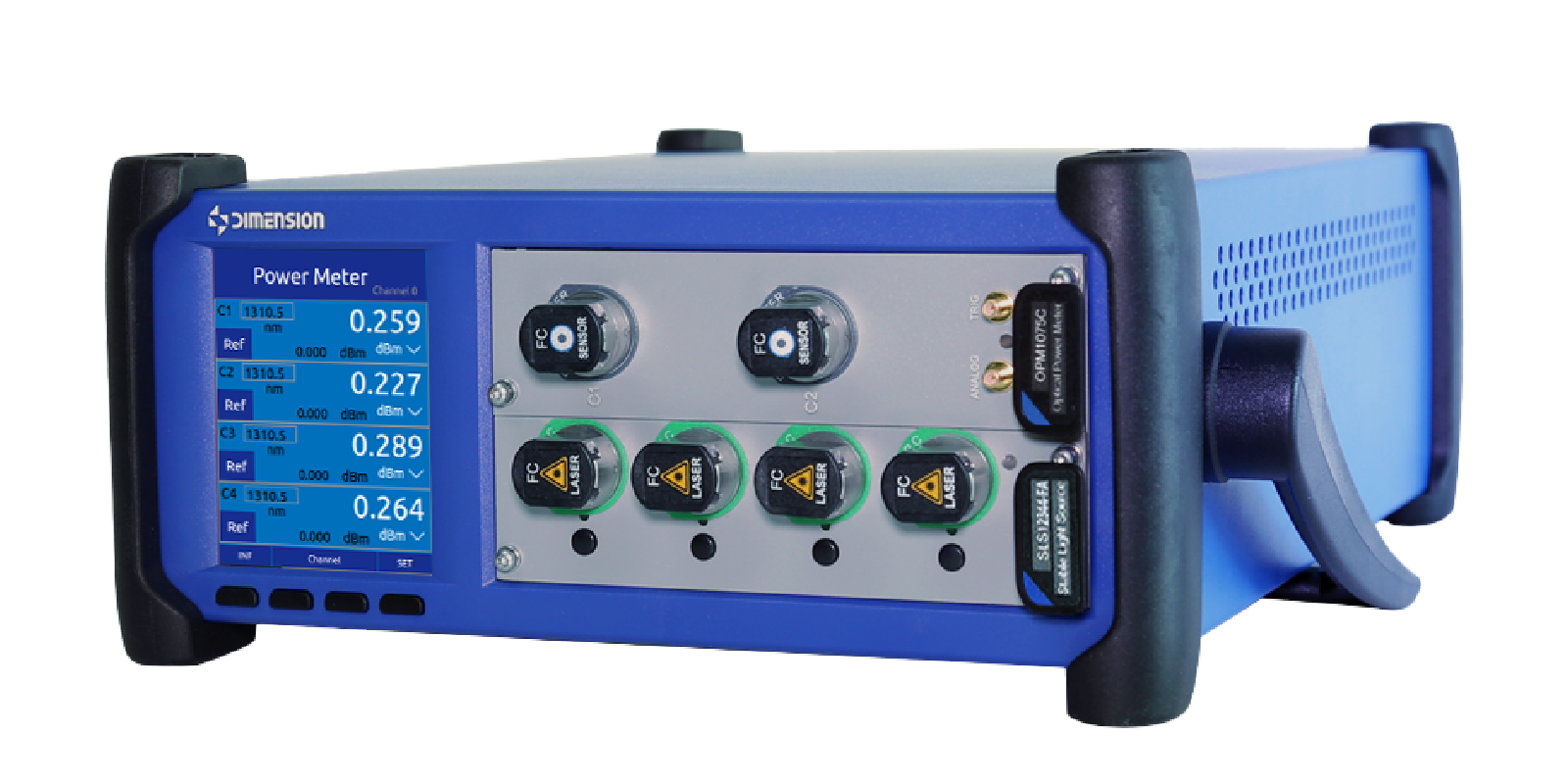
Figure 2 Example of Multi-channel Optical Power Collection Configuration
The reference settings should cover the variations in source power and the response differences of each detection channel. Port switching, range switching, and the status of the reference connector need to be included in the test conditions to avoid including the test link differences in the loss of the tested component.
Polarization-related loss test
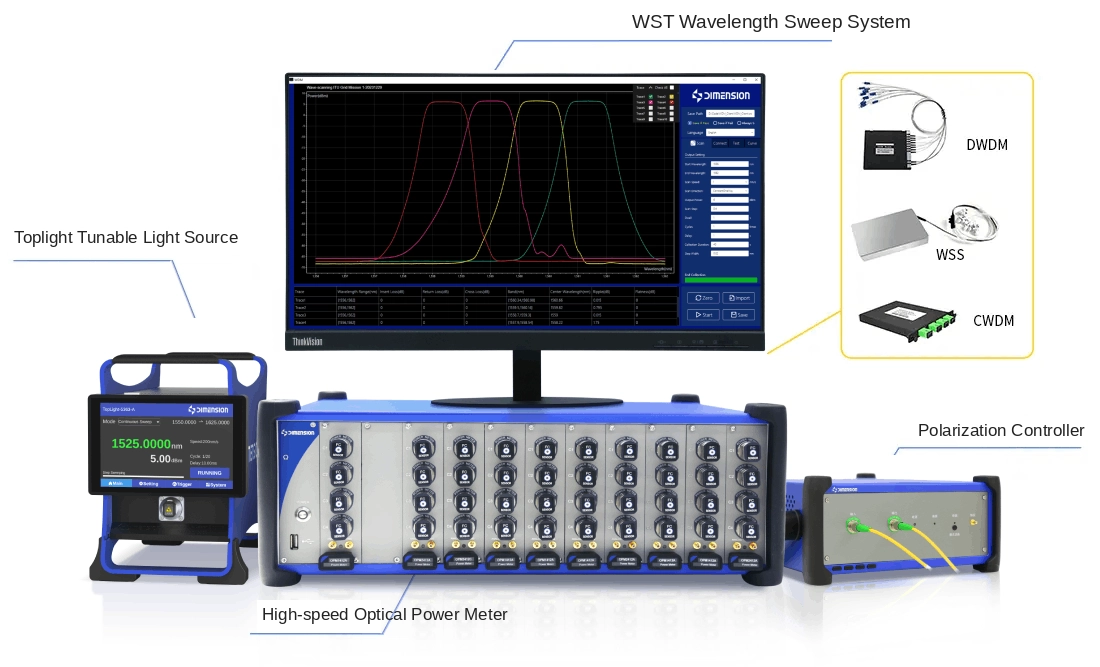
WST wavelength scanning system and PPC polarization controller
For single-mode devices, a combination of tunable light sources, polarization controllers, power acquisition and analysis software can be used to measure polarization-related loss (PDL) on each conducting route, evaluating the impact of changes in the input polarization state on the transmission loss. The Mueller matrix method with a known polarization state can be adopted according to project requirements to obtain the IL and PDL results for the specified wavelength or scanning band.
During the scanning process, keep the switch routing stable and synchronize the wavelength, polarization state and power data. Before the test, verify the reference link and polarization state generation conditions, and complete calibration and re-testing according to the actual connection status of each route.
Echo loss test
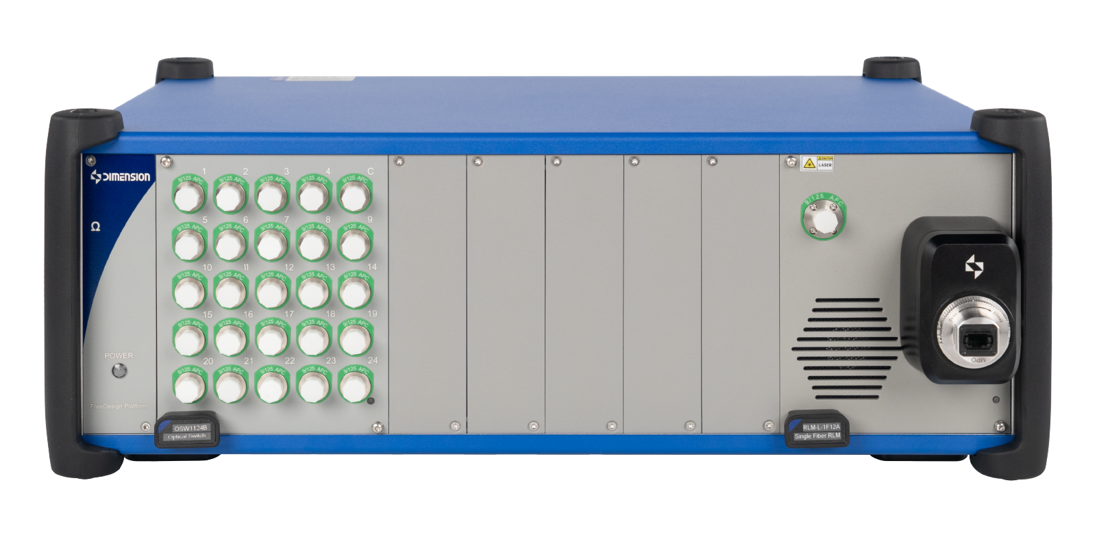
Insert the echo loss tester and the corresponding interface reference component
Measure the echo loss of the specified port under the specified switch state, and evaluate the reflection level of the device and the connection interface. Classify the conductive state, the off state and the input direction according to the test requirements, and record the measured port, routing state, wavelength and reference settings.
For devices with connectors, first complete the end face detection and cleaning, then set the test reference; when it is necessary to distinguish the contributions of the device body and the connection interface, a separate reference plane and test connection method should be defined.
Cross-talk and switching performance test
Cross-talk and turn-off isolation test
Stable light source and multi-channel OPM optical power meter
Inject an optical signal at the specified input port, measure the power at the target output port and the leakage power at the non-target ports, and evaluate the cross-talk. Compare the conductive and turn-off states of the same path, and define the evaluation of turn-off isolation as per the agreed definition; specify the reference power, port relationship and result symbol for both indicators.
Low leakage power test requires confirming the detection background noise, stray light and the leakage level of the test link, and avoiding strong light at the target port causing detection saturation. When no effective signal is detected, report the upper or lower limit according to the system measurement capability, and cannot directly record zero leakage.
Switching time and stabilization time test
High-speed OPM power acquisition and synchronous triggering configuration
Record the curve of output optical power changing with time synchronously based on the timing reference of the switching command or device control signal. Calculate the switching time according to the agreed rising and falling thresholds, and evaluate the stabilization time based on the condition that the output remains within the specified tolerance band and stabilizes.
The communication delay of the control command and the optical conversion process of the device should be defined separately. The sampling rate, detector bandwidth, and trigger accuracy are selected according to the device speed; when the power acquisition module is insufficient to distinguish the target transient, configure a higher bandwidth photodetector and acquisition equipment.
Switching repeatability and maintaining stability test
Light source, power acquisition and automated control software
For repeated entry on the same route, collect power after the specified stable waiting time, and statistically analyze the insertion loss changes in multiple switches; at the same time, continuously record power in the route-keeping state to observe the stability. During the test, synchronously monitor the source power changes, clearly define the cycle number, statistical scope and environmental conditions.
Life verification can be retested in stages according to the specified cycle number for IL, PDL, crosstalk and switching time, observing performance changes. Temperature conditions or reliability items are configured according to the device specifications and verification plan.
End-face inspection and cleaning
FastCheck Pro or MT SCOPE end inspection instrument and Offsoon Pro cleaning equipment
For devices with fiber optic connectors, complete the process of "inspection - cleaning - re-inspection" before connection and reference setup to reduce losses, reflections and repetitive abnormalities caused by contamination. Adapters, cleaning heads and processes are configured according to interface structures; bare fibers or internal optical paths of encapsulated devices are processed according to corresponding processes.
Advantages of the plan
Covering both static and dynamic performance
Incorporate IL, PDL, return loss, crosstalk, switching time and repeatability into the same test scheme, supporting R&D analysis and product determination.
Organize multi-channel data by routing
Based on input port, output port, switch status and wavelength correlation results, it is convenient to discover differences between routes and locate abnormal channels.
Support phased expansion
Start from fixed wavelength power testing, and increase wavelength scanning, polarization control, dynamic acquisition and loop verification as needed, matching different test depths.
Facilitate the establishment of an automated process
Combined with the modular platform and device control interface, it can be configured for route switching, stable waiting, data acquisition and report output, reducing repetitive operations.
Related products
Products and supporting equipment | Main application |
TLS tunable optical generator | Provide adjustable wavelength input and test the variation of IL with wavelength. |
WST Wavelength scanning system | Integrated wavelength scanning with IL and PDL analysis |
PPC polarization controller | Generate the polarization states required for the test and combine them with the PDL measurement. |
Multi-channel and high-speed OPM optical power meter | Conduction power, leakage power, stability and transient acquisition |
Return loss tester | Test of insertion loss and return loss under specified port and switch states |
OMEGA Modular testing platform | Integrate power collection and other modules to build a combined test system |
FastCheck Pro and MT SCOPE | Connector end face inspection and defect determination |
Offsoon Pro End face cleaning equipment | Cleaning of the end faces of the adapter connector |
Device driver, trigger and analysis software | Control the tested switch, organize the routing and correlate the test data |
The system band, detection dynamic range, number of channels, sampling bandwidth and control interface are all configured according to the requirements of the tested object.
Easily access services and support from Dimension
Want help or have questions?