
Fiber Optic Connectors & Assemblies
Fiber Array Unit (FAU) Testing Solutions (New)(New)
Polarization-Maintaining Fiber Connectivity Components (New)(New)
Fiber Array (FA) Spot Alignment and Coupling Inspection System
SN-MT Connector Inspection Solutions for Manufacturing
MMC Connector Cleaning and Inspection Solutions for Manufacturing
MPO Connector Inspection Solutions
Automated Cleaning and Inspection for High-Speed Optical Transceivers
1.6T/800G Single-core Optical Module Intelligent Cleaning and Inspection Solution
1.6T/800G LC Optical Module Testing Scheme
Optical Port Cleaning and Inspection for Active Optical Devices
High-Speed Coherent Optical Transceiver Testing
Active Optical Cable (AOC) Testing Solutions
Linear Pluggable Optics (LPO) Testing
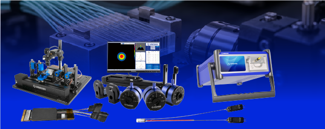
Polarization-Maintaining Fiber Connectivity Components (New)
Optical performance and end-face quality tests for polarization-maintaining jumper cables, polarization-maintaining connectors, and multi-channel polarization-maintaining connection components.
The polarization maintaining connection component connects the laser source, optical devices and the optical engine. Its quality is not only determined by the connection loss, but also related to the alignment of the polarization axis and the polarization retention ability. Dimension Technology combines polarization testing, insertion loss testing, end face detection and cleaning equipment around the polarization extinction ratio, polarization angle, insertion loss, return loss and end face quality to provide testing solutions for R&D verification, assembly debugging and finished product inspection.
Applicable test objects
Polarization maintaining optical fiber patch cords, polarization maintaining tail fibers, polarization maintaining connection component assemblies, as well as FAU, multi-core connection components and light source connection components using polarization maintaining optical fibers. Corresponding adapters and fixtures are configured for single-core, multi-core and bare-fiber output forms.

Figure 1 Test Process and Measurement Chain of Polarization-Conserving Connection Component
Test Focus
Polarization Performance Measurement: Focuses on the input light polarization quality, alignment of fast and slow axes, and the status of the tail fiber; Insertion Loss Measurement: Focuses on the reference setting and connection consistency; End-face Detection and Cleanliness: Conducts connection operation before and after testing. The results of each link are correlated by the test item number, port, and channel for easy anomaly location.
Solution Introduction
Polarization Absorption Ratio Test
PER Polarization Absorption Ratio Tester and Polarization-Conserving Test Light Source
The optical input component that aligns the polarization direction with the target axis of the tested item is used to measure the polarization absorption ratio of the output light using the PER tester, evaluating the polarization retention capability of the component. Before the test, verify the light source and reference link to avoid misjudging the insufficient input polarization quality or connection error as the performance of the tested item.
During the test, fix the wavelength, input axis, connection method, and tail fiber arrangement to reduce changes caused by bending, twisting, and clamping stress. For assembly process verification, compare the results before and after repeated insertion or re-clamping under specified conditions to evaluate connection consistency.
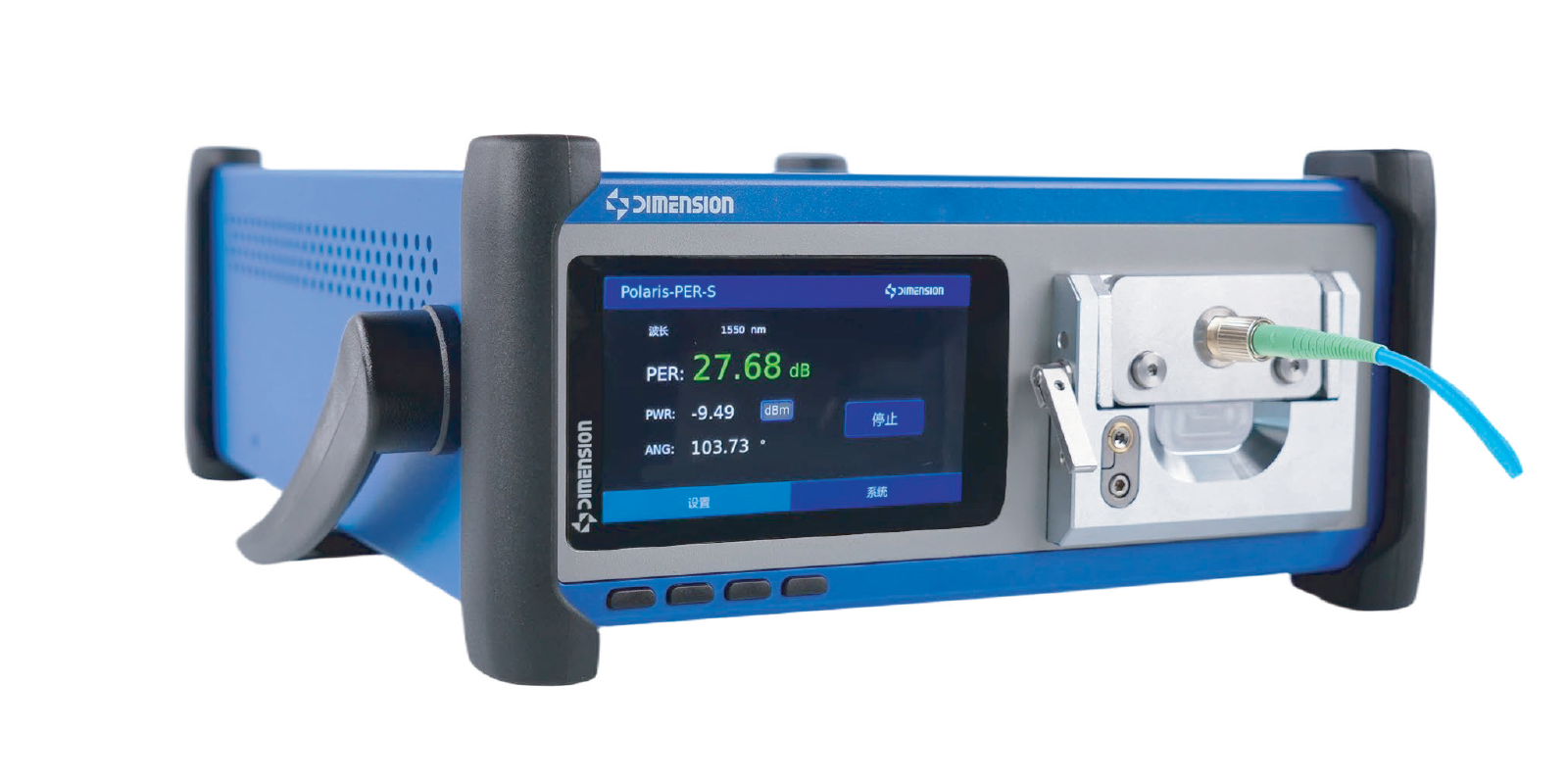
Figure 2 PER Polarization Absorption Ratio Tester
Alignment of polarization axis with connector key position test
PER Polarization Absorption Ratio Tester and angle positioning fixture
For connection components with key positions or positioning references, measure the angle of the output polarization direction relative to the mechanical reference, and check the assembly direction of the fast or slow axis. The test fixture needs to define the zero position and installation direction, and clearly specify the measured end, observation direction and target axis to avoid angle misjudgment due to inconsistent references.
For multi-channel output forms such as FAU, MT core inserts, etc., it is possible to combine rotational positioning and X, Y axis moving fixtures for core-by-core measurement, forming records of PER and angles for each channel; specific fixtures and test cycles are designed according to the fiber core arrangement and output form.
Insertion loss and return loss testing
Insertion loss tester and the corresponding reference components
Measure the optical power loss and reflection level after the connection of the measurement component, and check the connection quality. Set the reference link and test conditions according to the working wavelength, end face type and interface form of the measured object, record the insertion loss and return loss results for each port or channel, and correlate and analyze them with PER and angle results.
Polarization-maintaining components should clearly specify the input polarization state and axial condition during testing. Configure matching reference connectors at the PC and APC ends according to different interfaces, and complete the reference setting after the end face detection and cleaning are qualified.
End face quality and multi-channel testing
End face inspection and defect determination
FastCheck Pro fully automatic end face detector and MT SCOPE handheld end face detector
Check for end face contamination, scratches and other defects, reducing connection loss, reflection and repetitive anomalies. FastCheck Pro can be used for bench-top testing and automated integration, while MT SCOPE can be used for independent on-site testing; corresponding adapters can be selected based on single-core, multi-core and different connector structures.
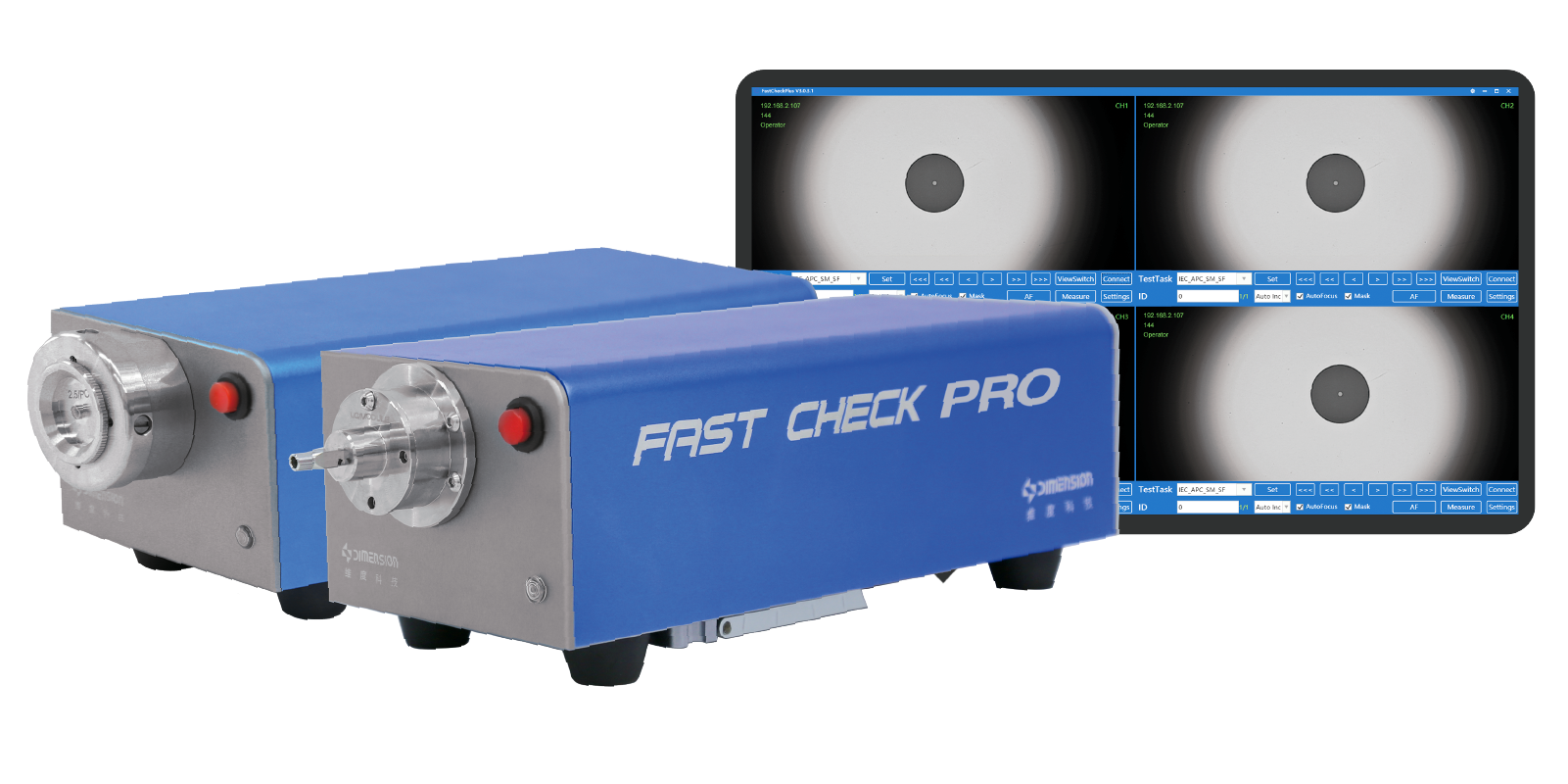
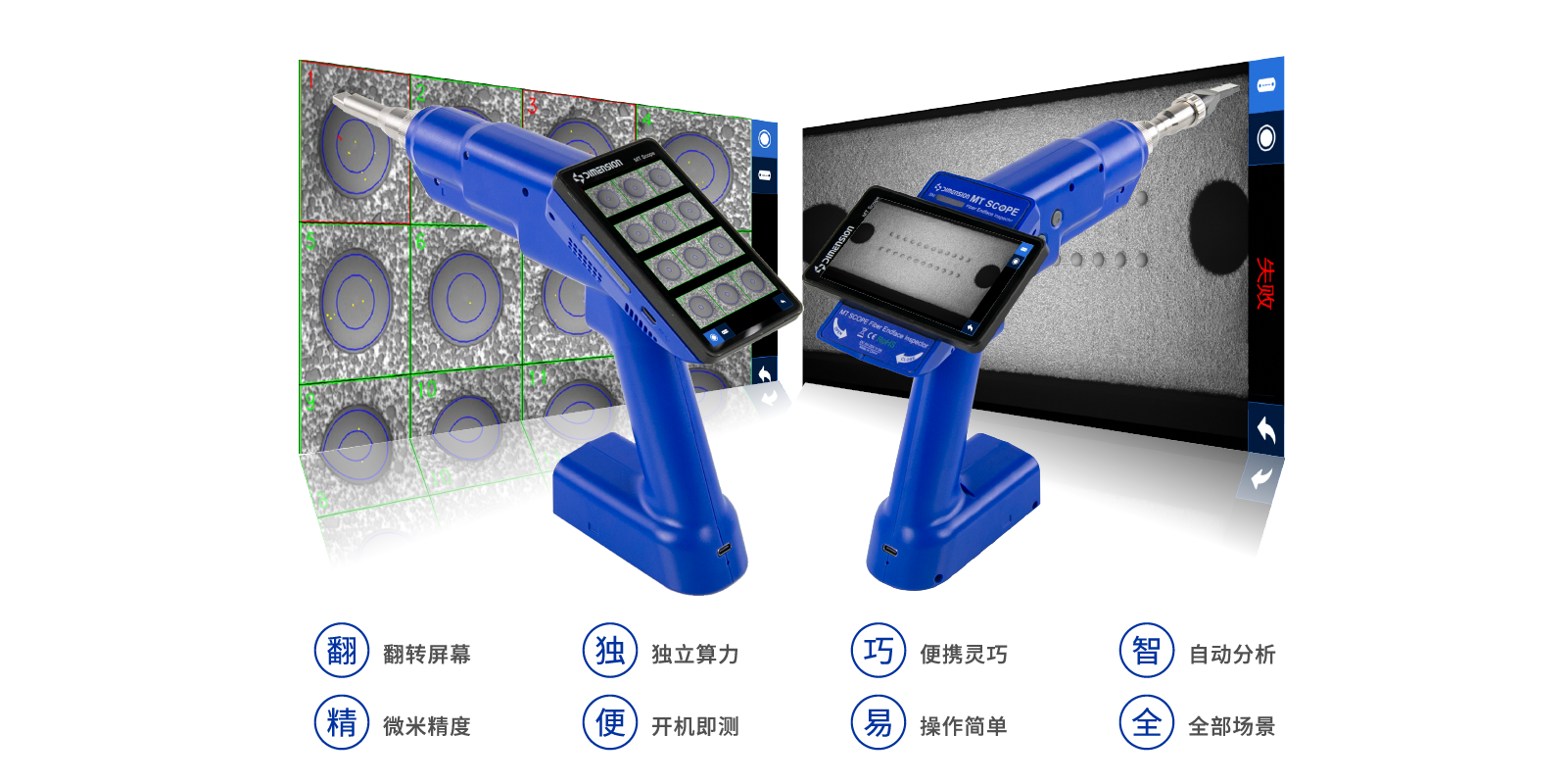
End-face defect detection is used to confirm the surface quality; the alignment of the connector key position with the polarization axis needs to be verified in combination with polarization measurement and angle positioning fixtures.
End face cleaning and re-inspection
Offsoon Pro Optical fiber end face cleaning equipment
For the compatible interface, a non-contact cleaning method using cleaning solution and dust-free gas is adopted. The end face status is confirmed according to the "inspection - cleaning - re-inspection" process. After re-inspection is qualified, it is connected to the test link to reduce test fluctuations caused by contamination and cross-contamination at the connection surface.
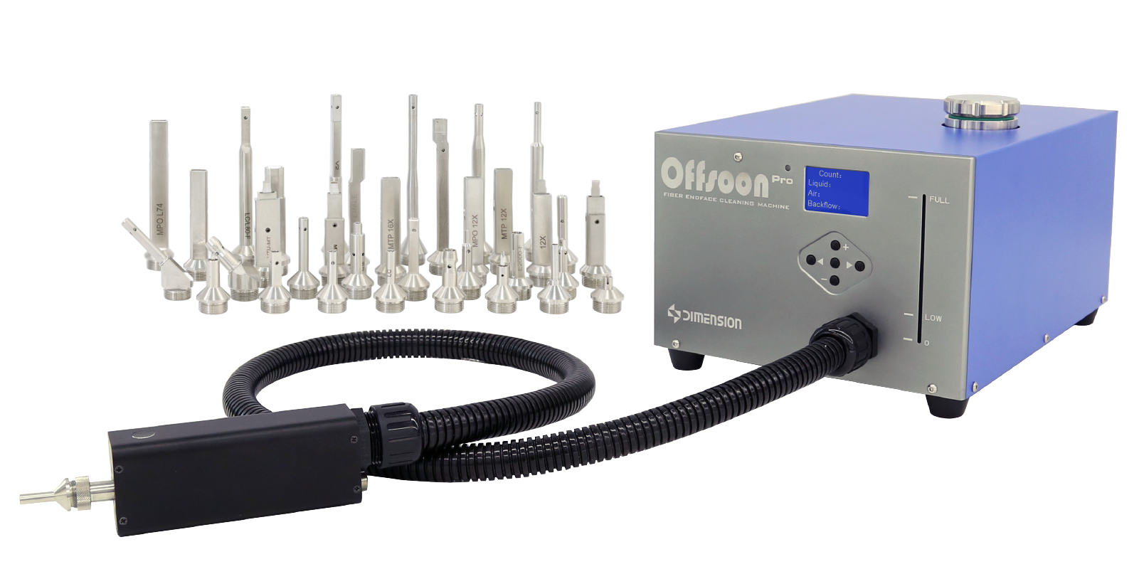
Figure 3 Offsoon Pro Fiber End Face Cleaning Equipment
Multi-channel switching and result correlation
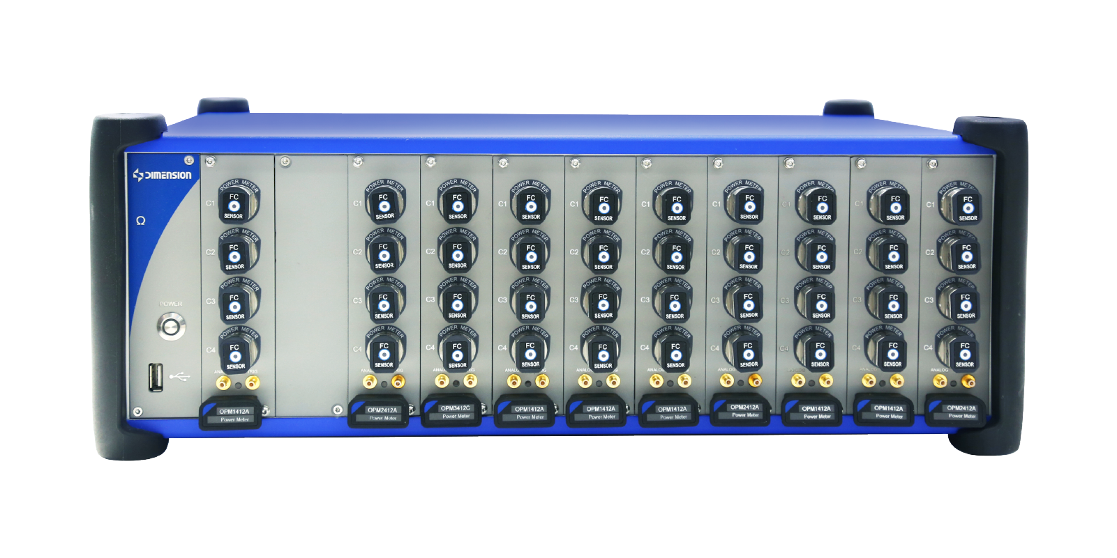
OSW Optical switch and OMEGA modular test platform
For multi-channel components, tests can be organized by combining the optical switch, power measurement module and upper computer software, reducing the need for repeated plugging and unplugging. PER tests need to verify the polarization maintaining capability of the optical switch and the entire connection link; based on the verification results, select the measurement to be conducted or complete the test by moving the fixture and connecting each port directly.
It is recommended to associate the end face images, PER, polarization angle, insertion loss and return loss data with "test item number - port - fiber channel", and retain the test wavelength, input axis and fixture reference, to facilitate R&D analysis and production traceability.
Advantages of the plan
· Coverage of polarization performance and connection quality
Incorporate PER, polarization angle, insertion loss, return loss, and end face quality into the same testing process, helping to distinguish issues such as axial assembly, connection loss, and surface contamination.
· Support assembly debugging and finished product inspection
During the development and assembly stages, observe the changes before and after axial adjustment. In the finished product stage, test and record the results of each port under unified conditions.
· Adapt to single-core and multi-channel components
Based on the interface, fiber core arrangement, and light emission form, combine the instrument, adapter, and mobile fixture to cover polarization jumpers and multi-channel polarization connection components.
· Facilitate the construction of consistent test records
Link the end face detection and cleaning results to the optical performance data, retain the test conditions and channel numbers, and provide a basis for abnormal retesting and quality traceability.
Related products
Products and supporting equipment | Main application |
PER Polarization Attenuation Ratio Tester | Measure the output extinction ratio and polarization angle |
Polarization test light source and reference component | Provide controlled input polarization and verify the reference link |
Return loss tester | Measure insertion loss and return loss |
FastCheck Pro End face detector | Desktop end face defect detection and automated integration |
MT SCOPE Handheld end inspection instrument | Independent operation of on-site end face inspection |
Offsoon Pro End face cleaning equipment | Cleaning of the end face of the adapter interface and subsequent re-inspection are carried out together. |
OSW optical switch and OMEGA platform | Multi-channel switching and combination testing, and the PER link needs to be verified |
Angle positioning and X/Y axis moving fixture | Establish a mechanical angle reference and position the multi-channel output |
The system wavelength, range, accuracy, interface and timing are determined according to the requirements of the measured object; the multi-channel fixture and software process are configured according to the project.
Easily access services and support from Dimension
Want help or have questions?