
800G Optical Module Testing Pitfall Avoidance Guide: Missing these 6 steps could result in a 50% drop in yield!
2026.01.07


In the field of optical communication, as the data rate keeps soaring, the complexity of testing has increased exponentially. Whether it is for research and development verification or production line mass production, a clear and comprehensive testing plan directly determines the product's yield and the speed of its launch. When engineers set up the testing platform, they often fall into the trap of "having equipment but no logic" - they simply pile up instruments without considering the completeness of the test dimensions and the consistency of the process.
To help everyone clarify their thinking, today we won't talk about the abstract. Instead, we will directly present the "core six-step method" for testing 800G optical modules. This plan covers the entire link from basic optical power to port maintenance. We recommend saving it for future use!

This issue's theme: The complete architecture of the 800G optical module testing process
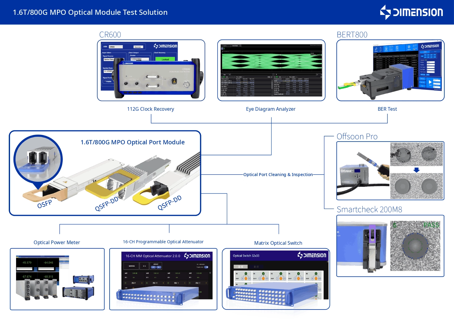
A complete testing plan is not merely a list of equipment; it involves a comprehensive control over signal quality, transmission performance, and the physical environment. We have broken it down into the following 6 core dimensions:
01 .
Test of Tx emission power
Core concern: Whether the "physical strength" of the signal meets the standards.
This is the most fundamental and crucial step. If the optical power at the transmitting end is not within the standard range, all subsequent tests lose their significance.
Corresponding instrument: Optical Power Meter
Function: Accurately measure the optical power value at the transmitting end to ensure that the signal strength meets the specification requirements.
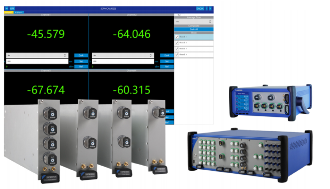
The OPM optical power meter series modules of the dimension range include multiple series types. Through the platform-based testing solution, it can provide rapid, accurate and flexible power measurement.
02 .
BER bit error rate test
Core focus: "Accuracy" of signal transmission.
Just having power is not enough; it is also necessary to check if there are any errors in the data transmission. The bit error rate directly reflects the transmission quality of the link.
Corresponding instrument: Bit Error Meter (used in conjunction with an attenuator)
Function: The bit error meter is used to send and receive test code patterns, and through comparison and analysis, it can detect the error situation; the attenuator is used to simulate the signal attenuation after long-distance transmission, testing the anti-noise ability of the module.
The BERT800 series of bit error meters from Dimension Technology combines a general control board and interface boards for different optical block models into a high-speed optical transceiver module testing platform, capable of testing the bit error rate, configuring module parameters, monitoring module operation status, etc. Choosing the appropriate complete machine type can be used for batch production or performance verification, reliability verification, and other different usage scenarios in conjunction with the thermal flow meter.
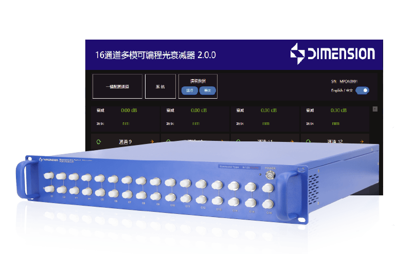
In addition, we offer the POA multi-channel programmable optical attenuator. The multi-channel attenuator features high reliability, high attenuation accuracy and response speed, and provides a wide attenuation range, which meets the testing requirements of high-speed optical modules. The rack-mounted design also facilitates quick deployment for customers and supports customization of the number of channels.
03 .
Eye diagram and TDECQ analysis
Core focus: The "appearance level" and "healthiness" of the signal.
The eye diagram is an intuitive means of measuring signal quality, while TDECQ (Transmitter Dispersion Cost Equivalent Value) is a mandatory test metric for 800G and other high-speed rate modules, which quantifies the signal's tolerance to dispersion.
Corresponding instruments: CDR (Clock Data Recovery Module), Oscilloscope
Function: The CDR is responsible for extracting the clock from the signal and restoring the data, while the oscilloscope is used to display the eye diagram and calculate the TDECQ value. (Note: If conditions are limited, this part can be an optional or R&D-level test.)
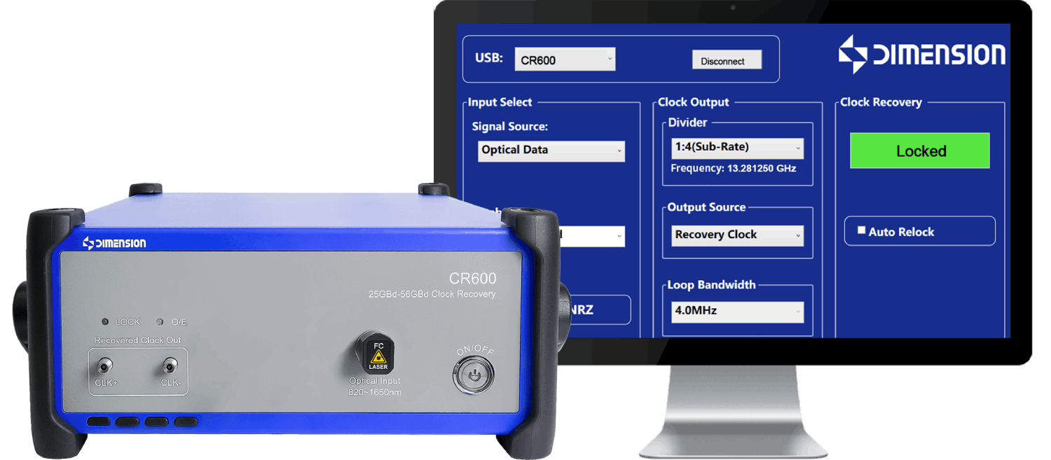
Dimension Technology's CR600 photoelectric clock recovery unit supports NRZ and PAM4. It can restore the photoelectric clock signal within the 60Gbd range. The system integrates a single multimode photoelectric conversion and clock recovery circuit, which can be applied simultaneously in electrical and optical applications. It meets the requirements of high sensitivity and low inherent jitter, and has excellent measurement accuracy.
04 .
Optical path switching and multiplexing
Core focus: Test efficiency and multi-channel management.
In mass production or large-scale verification, it is impossible to provide a set of instruments for each port, so an automated switching solution is required.
Corresponding instrument: Optical switch
Function: Achieve automatic switching of multiple optical signals, allowing a single test instrument to alternately test multiple modules, significantly improving test efficiency.
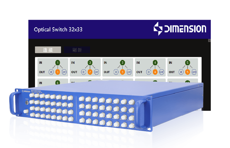
The Dimension Technology OSW matrix optical switch offers a wide range of options and customization solutions that can meet all the optical path switching requirements of customers. Moreover, for customers who need light monitoring, a power monitoring solution has been added to facilitate the setup of the testing system.
05 .
Optical port cleaning
Core concern: "Hygiene" at the physical layer.
Dust and stains are the number one killers of optical communication. Tiny particles can cause connector wear and even damage the laser.
Corresponding instrument: Fiber optic end face cleaning machine function: Standardize the cleaning of the end faces of optical modules to avoid secondary pollution caused by human operations.
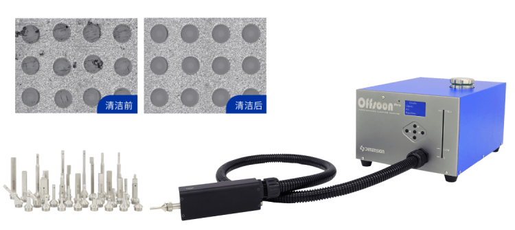
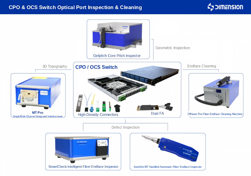
The Offsoon Pro fiber end face cleaning machine of Dimension Technology adopts the principle of liquid + gas cleaning. The cleaning solution can quickly dissolve the stains on the fiber end face, and the dust-free gas sprayed will blow away the cleaning solution and the oil stains. The entire cleaning process only takes 2 seconds, and the single cleaning efficiency is over 98%, reaching the leading level in the industry.
06 .
Optical port detection
Core focus: "Physical examination" at the physical layer.
After cleaning, a check must be conducted to ensure that there are no scratches, stains or damages on the end face.
Corresponding instrument: Fiber optic end face tester
Function: Through microscopic imaging technology, it visually presents the status of the fiber optic end face, ensuring the reliability of the physical connection.
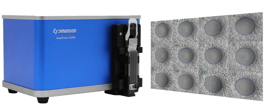
The Dimension SmartCheck intelligent optical fiber end-face detector can perform automatic and rapid detection of dirt spots and scratches in terms of size and quantity, and it also outputs measurement reports for easy traceability and analysis.
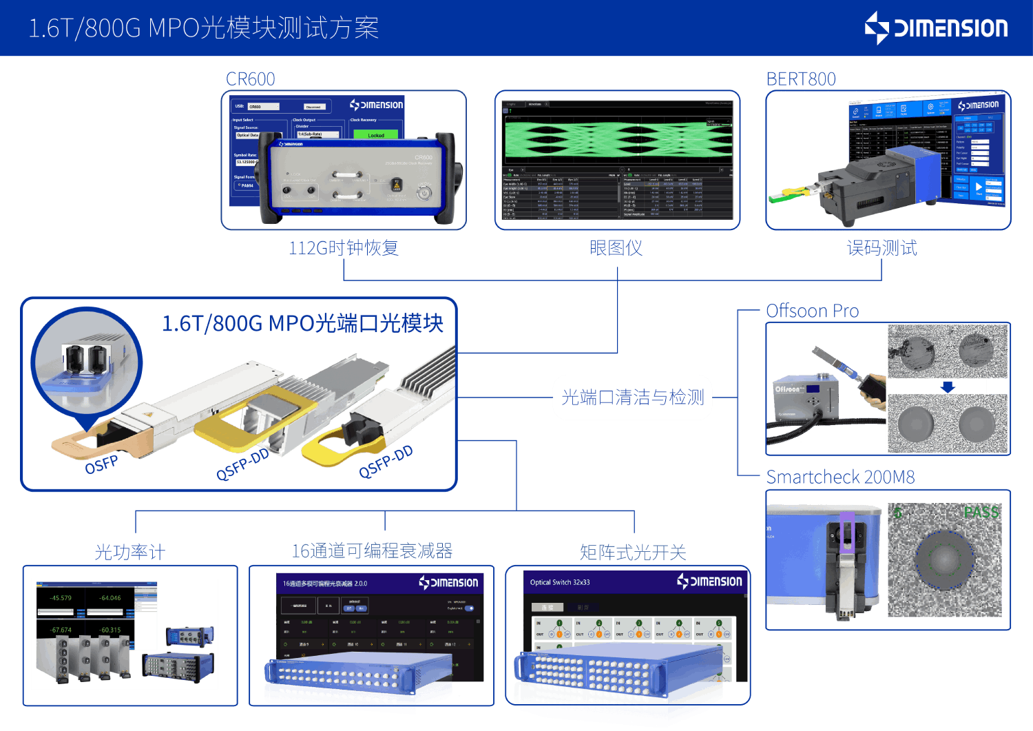
One picture explains it all: Test and Equipment Correspondence Table
To facilitate everyone's reference and selection, we have organized the above content into a table:
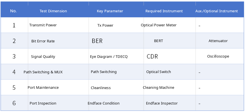
Final Note: Optical module testing is a systematic process. "Stacking the instruments" does not equate to "comprehensive testing"!
When setting up the platform, you can first draw a "test overview diagram" to clarify the purposes of each step, and then configure the corresponding instruments.
Especially for high-speed modules of 800G and above, the cleaning and detection of the physical layer are often overlooked, but this is precisely the hidden threshold for ensuring yield!
We hope this summary can bring some inspiration to your testing work. If you have specific testing problems, please feel free to contact us for discussion and exchange!

More news recommendations
-
In the Era of AI Computing, Optical Interconnect Quality Gets an Upgrade!
2026.10.16
-
800G Optical Module Testing Pitfall Avoidance Guide: Missing these 6 steps could result in a 50% drop in yield!
2026.01.07
-

An Introduction to the 2023 Nobel Prize in Physics: A First Look at Attosecond Lasers!
2023.10.26
-
800G Optical Module Test Solutions: Meeting the Demands of High-Speed Optical Communication!
2023.08.13